This website uses cookies so that we can provide you with the best user experience possible. Cookie information is stored in your browser and performs functions such as recognising you when you return to our website and helping our team to understand which sections of the website you find most interesting and useful.
Basics of PID Controllers: Design, Applications, Advantages & Disadvantages


Timur Yuldashev
IT Writer, PhD in Philological Sciences

Andrey Solovev
Chief Technology Officer, PhD in Physics and Mathematics
- What is a PID Controller?
- How Does a PID Controller Work?
- Proportional, Integral, and Derivative Terms
- Basics of PID Controllers: Applications
- Basics of PID Controllers: Advantages and Disadvantages
- Types of PID Controllers
- Basics of PID Controllers: Real-Life Implementation
- Alternatives to PID Controllers
- Conclusion
- What is a PID Controller?
- How Does a PID Controller Work?
- Proportional, Integral, and Derivative Terms
- Proportional term
- Integral term
- Derivative term
- Basics of PID Controllers: Applications
- Basics of PID Controllers: Advantages and Disadvantages
- Types of PID Controllers
- Basics of PID Controllers: Real-Life Implementation
- Alternatives to PID Controllers
- Conclusion
Proportional–integral–derivative controllers have been in use since the beginning of the 20th century. They find applications in almost any area where automatic control is required. As of 2021, the global PID controller market was estimated at $1.42 billion and is forecasted to reach $1.94 billion by 2029. In this article, we will explain the popularity of this mechanism and cover the basics of PID controllers: their working principle, types, and applications. We will also touch upon their pros and cons, implementation peculiarities, and alternatives.
- What is a PID Controller?
- How Does a PID Controller Work?
- Proportional, Integral, and Derivative Terms
- Proportional term
- Integral term
- Derivative term
- Basics of PID Controllers: Applications
- Basics of PID Controllers: Advantages and Disadvantages
- Types of PID Controllers
- Basics of PID Controllers: Real-Life Implementation
- Alternatives to PID Controllers
- Conclusion
What is a PID Controller?
PID controller is a mechanism used in feedback control loops to automatically maintain a process parameter at a certain level. About 90% of all automatic control systems have this universal mechanism.
In simple terms, the PID algorithm regulates a process variable by calculating a control signal that is the sum of three terms: proportional, integral, and derivative. Hence its name. As a result, it can return a process variable into the acceptable range.
Our team has used this mechanism in many projects, as it is a simple and affordable solution. If you need to design a device with a control system, contact us to discuss whether this solution will suit your case.
How Does a PID Controller Work?
To understand how a PID controller works, one needs to see what is happening inside a closed loop system first.
The PID controller is placed in the core of a closed loop system. It can be a device or an algorithm running on a microcontroller. The plant/system refers to the object under control which can be an industrial furnace, a motor, or anything else. The plant is controlled with an actuation device, which can be a motor drive, a heater, a cooler, or anything else that can drive the system. The parameter that needs to be controlled is called the process variable. It can be temperature, flow rate, pressure, rotation speed, etc.
The process variable is measured with a sensor that sends the signal back to the controller, thus providing feedback. The controller receives a desired process value or set point. It is the value that the system must achieve. This parameter is always set from outside – manually or automatically by a high-level control system (e.g., MPC controllers in the chemical industry).
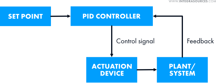
The controller compares the measured process variable and the set point. Based on the difference between them, the algorithm computes a control signal and sends it to the actuation device. It, in turn, drives the plant to the desired process value (set point). This is the basic working principle of a PID controller.
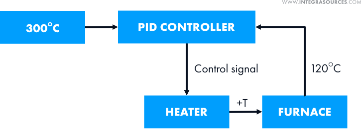
As the algorithm deals with numbers, it doesn’t matter to which kind of process it is applied. That’s why the mechanism is widely used in electronics development.
Proportional, Integral, and Derivative Terms
A PID controller calculates the control signal based on three control terms: proportional, integral, and derivative. To compute the output, the algorithm simply multiplies each of them by a gain and sums these three addends.

If a gain is set to zero, the whole term becomes zero. This way, the PID mechanism can be turned into a P controller, a PI controller, and other modifications.
Proportional term
The proportional term is the difference between the set point (SP) and the measured process variable (PV) multiplied by the P gain (Kp). This difference is referred to as the error value, or e(t).

The error value represents how far the system is from the desired value. The higher it is, the higher the value of the manipulated variable and the faster the system will drive the process variable to the desired value. In the heating process shown below, the manipulated variable drops as the measured process variable (temperature) rises.
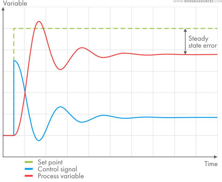
The proportional gain (Kp) defines the speed of the control system response. But if it is too large, the process variable starts to oscillate and can even oscillate out of control.
In certain systems, using only the P term cannot reduce the error value to zero. The remaining difference between the set point and process variable is called the steady-state error. In such cases, we need to add the integral term to the equation.
Integral term
The P term takes into account only the current error value. The integral term is proportional to the time integral of the error value. It means the I component considers the history of the error. The integral gain (Ki) increases the weight of this component in the actuating output.

If there is even a small error, the integral term will increase continuously (or decrease if the error is negative) until the steady state error equals zero. The plot below shows the work of a pure I controller.
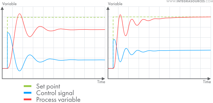
The plots below show the work of a P controller (on the left) and a PI controller (on the right) with the same P gain. As you can see, the process on the left causes a steady-state error. But adding the I term eliminates the error (graph on the right).
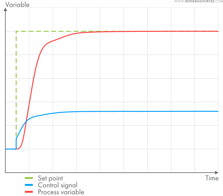
By properly adjusting the gains, one can make a transient response monotonic if required:
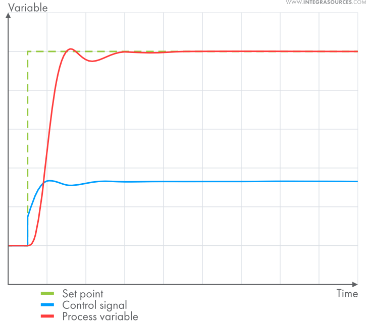
Or you can make a fast transient response with no oscillations. The properties are defined by the requirements for the system.
Derivative term
The derivative term uses the difference between the current and previous error values divided by the time between measurements (dt).

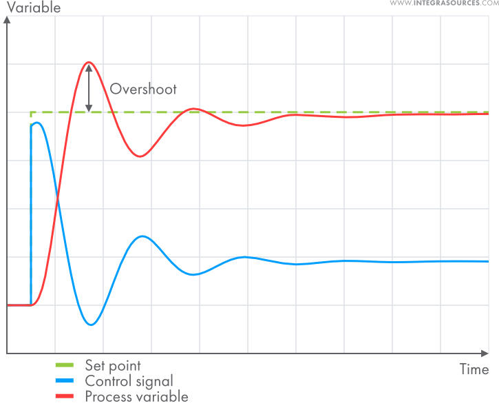
It is proportional to the rate of change of the process variable. While the P term fixes the current error and the I term considers previous errors, the derivative term takes into account future error values. The D component compensates for the sharp fluctuations in the system, prevents it from strong overshoot, and decreases oscillations. The derivative gain (Kd) changes the weight of this component in the control signal.
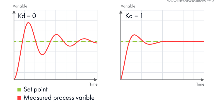
The D term is important for systems that face violent changes, such as quadcopters. At the same time, it amplifies measurement noise and external disturbances. Often, the D term is left out when dealing with slow systems.
Basics of PID Controllers: Applications
Universal PID controllers can quickly drive the process variable into the acceptable range, keep this value at the desired level, and respond to disturbances quickly. In some cases, applying a P-only controller or a PI controller is enough. But when you need better stability or tracking, which requires eliminating undesirable overshoot, the use of a PID controller is a better option. Contact our team to tell us about your project, and we will find the most suitable solution.
These features make PID controllers good for a variety of applications.
- Manufacturing
The algorithm allows for regulating various parameters in manufacturing equipment, such as pressure, flow rate, voltage, etc. The use of PID controllers for temperature control is especially important in the metallurgical industry. Heat treatment of metals often requires high precision.
- Chemical and pharmaceutical industries
Here, the mechanism allows chemists to regulate pressure, temperature, PH, and humidity in different chemical processes. It is also used to control the flow rate of fluids to achieve the desired concentration of chemicals.
- Autopilot
Any self-driving vehicle, from a car to a plane, can’t move with perfect precision. Its trajectory is affected by the environment, so the vehicle needs corrections. This need explains the use of PID controllers in the aircraft and automobile industries. The cruise control system of a car is a good example of basic PID control. The mechanism also finds applications in hoverboards, quadcopters, as well as plane and drone autopilots.
We used a PID controller as part of a drone autopilot system – one of our embedded hardware design projects. We needed to control the spatial attitude of the drone. Otherwise, it would drift away or start rotating. To do that, we implemented the PID algorithm on the drone’s microcontroller. The process variable is calculated by a direction cosine matrix (DCM) based on the data from the gyroscope and accelerometer. The PID controller increases or decreases the motors’ thrust, thus stabilizing the drone’s spatial attitude and its airframe dynamics.
We used the same PID mechanism for our ready-to-fly quadcopter project.
- Robotics
The use of PID controllers in robotics development allows achieving high accuracy of movement. Depending on the application, it can be sufficient to apply a P-only or a PI modification.
Using a PID controller for DC motor control is another frequent application. Our team applied this algorithm when developing a DC motor controller for a company that makes robots and robot kits.
The PID algorithm was implemented on the microcontroller of the device. Its task was to regulate the rotation speed of DC motors. The process variable is measured with a quadrature encoder. The solution allows for a smooth start/stop, stabilizes the speed of a robot, and even provides distance control.
Since the DC motor controller was supposed to be used with different robot models, we also created a desktop application for setting the parameters of the device. The app also allows for tuning the PID gains.
- Power conversion
The PID algorithm can be incorporated into power converters to make energy consumption more efficient by regulating the output voltage. That’s why it is used both in consumer-grade solutions and industrial power electronics development.
- Photovoltaics
The power output of solar panels depends on the weather. Tracking the highest power point of a PV cell allows for maintaining stable current and voltage. PID controllers reduce the response time of the system.
Basics of PID Controllers: Advantages and Disadvantages
The PID algorithm is universal. It suits almost any kind of process as long as the desired effect can be achieved by forcing the process variable to match the desired value sooner or later. Here are some of the key advantages of this control technique:
- PID provides greater accuracy than simpler on/off controllers.
- The algorithm is more energy efficient.
- It isn’t heavy on hardware, so devices with PID controllers are mostly cheap.
- The algorithm can be implemented as analog electronics, digital electronics, and mechanical solutions. Today, engineers mostly use digital PID controllers, but there are also pneumatic, hydraulic, and mechanical PID controllers.
- The P, I, and D components can be tuned intuitively, by trial and error. Even if tuning the PID controller in a control system does require a specialist, one session should last for years.
- More advanced controllers will probably require stopping the process for re-tuning. But a universal PID controller can often be re-tuned while the process is still running, which is often more convenient.
- Unlike simpler solutions, the PID algorithm can substantially extend the life of an actuation device.
- While advanced controllers are more efficient, using them may not be worth the expense and effort.
- Unlike model-based controllers, the PID algorithm responds to unmeasured disturbances better due to having proportional and derivative actions.
- The PID algorithm has been in use for over 70 years, so engineers have found workarounds for many of the existing problems.
At the same time, there are situations when a PID controller is not the best choice.
- If not tuned properly, the algorithm can make the system unstable and even damage it.
- PID controllers amplify the high-frequency content of the error signal. This boosts the noise component of the control output, which destabilizes the system.
- The PID technique suits single input, single output (SISO) systems. But classic PID controllers don’t do well if there’s a need to control more than one parameter.
- The unmodified PID algorithm performs poorly when the delay between the output and the process response is too long. But the problem can be solved by augmenting the mechanism with additional intelligence.
Our team has great experience in this field. Often, we used the PID algorithm as part of an advanced control system by combining it with other techniques. Feel free to contact us and ask any questions about the device you want to create.
Types of PID Controllers
PID controllers use proportional, integral, and derivative components to regulate a process. By setting a gain to zero, one eliminates the term from the equation. Such types of PID controllers are called PID modifications. Engineers generally use the following modifications:
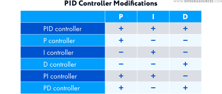
- A proportional controller reduces the rise time (time required for the process variable to reach the set point) and speeds up the response.
When our team developed hardware and software for an autonomous lawn mower, it decided to use a P controller for regulating the robot’s movement speed. Stable speed allowed the mower to cut grass more efficiently.
The motor of the lawn mower is equipped with a quadrature encoder. The data from this sensor is fed to the PID algorithm implemented on the microcontroller of the device. The control signal regulates the voltage applied to the motor, thus controlling the speed. In this project, we didn’t need high accuracy, and even a small steady-state error was not a problem. That’s why the team didn’t use the I and D terms.
The same solution was applied to the recharging system of the lawn mower.
- A derivative controller minimizes the overshoot and oscillations in the output of the system.
- An integral controller reduces the time-invariant error and lags the output phase.
- A PI controller allows for reducing the rise time and eliminating the steady state error.
- A PD controller reduces the rise time, overshoot, and oscillations in the plant.
Apart from these modifications, there are types of PID controllers augmented with more complicated algorithms. They can perform tasks with which the classical PID algorithm cannot cope.
Basics of PID Controllers: Real-Life Implementation
The working principle described above is a theoretical idealization of the process. In actual embedded electronics development, one has to take into account real-life working conditions, limitations, and various features of the environment. Engineers generally face the following problems.
1. In a mathematical model, the actuation device would change the process variable within any range of values defined by the control signal from the PID controller. But, in reality, the dynamic range of physical variables is finite. A motor has limited power, a valve has limited throughput, etc.
2. In real life, a control system may be unable to change the sign of the manipulated variable. For instance, many temperature regulation systems don’t have cooler devices. So, if the control signal is less than zero, the system can only turn the heater off.
3. The limited accuracy of measurements requires additional efforts so that differentiation operations could be performed with permissible error.
4. Almost any system has nonlinearities: saturation, the rate of rise limitation, hysteresis, and slacks.
5. Parameter spread and random parameter variations of the controller and plant.
6. Discrete implementation of the controller.
7. The need for bumpless switching between control modes.
Alternatives to PID Controllers
Many control techniques can serve as alternatives to the PID algorithm. While some of them offer higher efficiency, such solutions are usually more expensive.
- On-off controllers
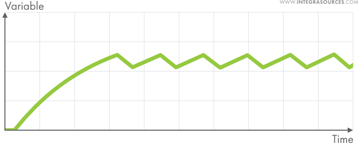
They can execute only two types of outputs: fully on (when the process variable is not reached) and fully off (when the error is zero or negative). Such solutions are cheap and simple but offer poor accuracy. They often can’t keep the process variable at a certain level due to inertia. The parameter will go above and below the set point all the time (this effect is called “hunting”). But on-off controllers suit systems where precise control is not required.
- Fuzzy logic controllers
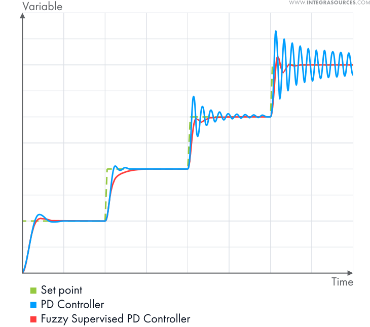
Digital logic uses discrete values (0 or 1). Fuzzy logic operates on continuous values between 0 and 1. In practice, most FLCs are PID controllers modified with fuzzy logic to schedule the gains. Variable gains work better for nonlinear processes. This solution suits complicated systems that have lots of uncertainties or variability.
- Optimal control techniques
Optimal controllers include a wide range of types: model predictive, linear–quadratic–Gaussian (LQG), H-infinity controllers, and many nonlinear optimal controllers, including sliding mode controllers according to some specialists. Optimal controllers are more efficient than the PID algorithm. On the other hand, implementing them is much more complicated and expensive, which is why they are mostly applied to complicated MIMO systems.
Conclusion
A PID controller is a closed feedback loop system that can control a plant based on the measurement of the process variable. Since it deals with numbers only, it can be applied to almost any process.
The PID algorithm has been in use for over 70 years. Despite that, it remains the most popular solution in almost any industry. PID controllers are used in metallurgy, chemical, pharmaceutical, and automotive industries, as well as in robotics, power conversion, photovoltaics, and other spheres.
Although there are many advanced alternatives, the basics of PID controllers are easier to understand. These solutions are affordable and easy to implement. The PID gains can often be tuned by trial and error. Unless optimized efficiency is a must, a proportional–integral–derivative controller should be sufficient. Our team has used PID controllers in many projects that required a control system. We have enough experience to understand when and how to use it, or how to modify it to achieve the highest efficiency. Contact us directly to discuss your project and possible solutions.
Share this article


Related
materials
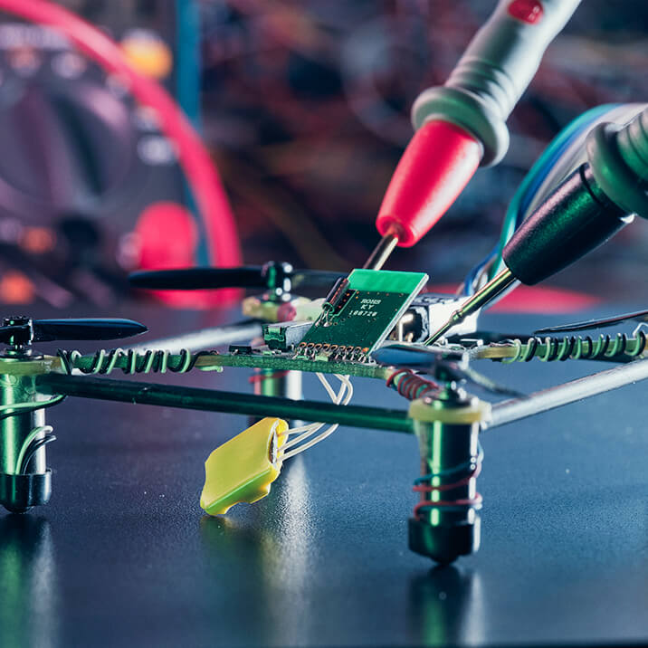
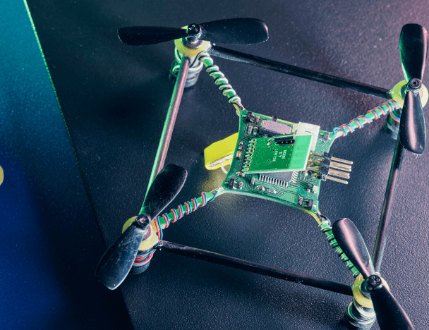
A Ready-To-Fly Quadcopter
The quadcopter is 10x10 centimeters in size. It can be controlled over a Sony PlayStation 2 gamepad or any other...
LEARN MORE
LEARN MORE


Mathematical Representations of PID Controller Gains
PID controllers find many uses in various industries. In this article, we discuss the mathematical representations of PID controller gains...
LEARN MORE
LEARN MORE

What Makes Electronics Prototyping so Important for Successful Product Development?
Electronics prototyping answers a range of crucial questions, such as how to solve a particular engineering problem, how to do...
LEARN MORE
LEARN MORE

